Documentation (Guidelines)
- Jesilyn Barnes (Deactivated)
- Anonymous
Information Architecture
How to present the content and information for a design (Incapsulating all form validation in one column for now)
UX General Deliverables
https://www.smashingmagazine.com/2017/09/comprehensive-overview-ux-design-deliverables/
https://uxplanet.org/a-complete-list-of-ux-deliverables-d62ccf1de434
https://uxdesign.cc/ux-design-methods-deliverables-657f54ce3c7d
https://www.toptal.com/designers/ux/10-common-ux-deliverables
UX Strategy Deliverables
IA Deliverables
https://www.sitepoint.com/architecture-deliverables/
https://www.uxbooth.com/articles/complete-beginners-guide-to-information-architecture/
http://www.fatpurple.com/2010/03/01/web-information-architecture-deliverables-and-diagrams/
Content Modeling
http://www.uxforthemasses.com/resources/example-ux-docs/
https://alistapart.com/article/content-modelling-a-master-skill
https://www.contentstack.com/docs/knowledgebase/content-modeling
https://contentstrategy101.com/contents/developing/architecting-a-solution/content-modeling/
Types of Diagrams
- Flowcharts
- Wireframes
- Wireflows / Screenflows
![]() https://medium.com/sketch-app-sources/user-journey-maps-or-user-flows-what-to-do-first-48e825e73aa8
https://medium.com/sketch-app-sources/user-journey-maps-or-user-flows-what-to-do-first-48e825e73aa8
User Flows (Flow Diagrams)
User Flows, called also UX, Wire, UI or IX Flows are the deliverables visualizing the complete path that users follow across the whole solution.
Their origins are flow charts, but through years they have been enriched with more visual elements — wireframes/mockups or gesture visualization.
UX Flows
Hybrid between traditional flow charts with some visual interfaces included in them. They focus on a task to be accomplished by the user and eventual alternative paths.
UX Flow may not be linear — it contains decision nodes, paths, modes, and loops that show all possible interactions with the product.
Usually flows do not focus on users feeling or multiple layers of the solution. Their main purpose is to visualize the flow through the solution.
Journey Maps focus on more on the experience of the customer, try to detect pain points or moments of delight. They may focus on different aspects of a solution, not only the mobile app but also the back-end server.
While User Flows have got more formal rules (probably because their flowchart origins), Customer Journey Maps are very various. There are examples around the web of maps that are very different from each other.
Flowcharts
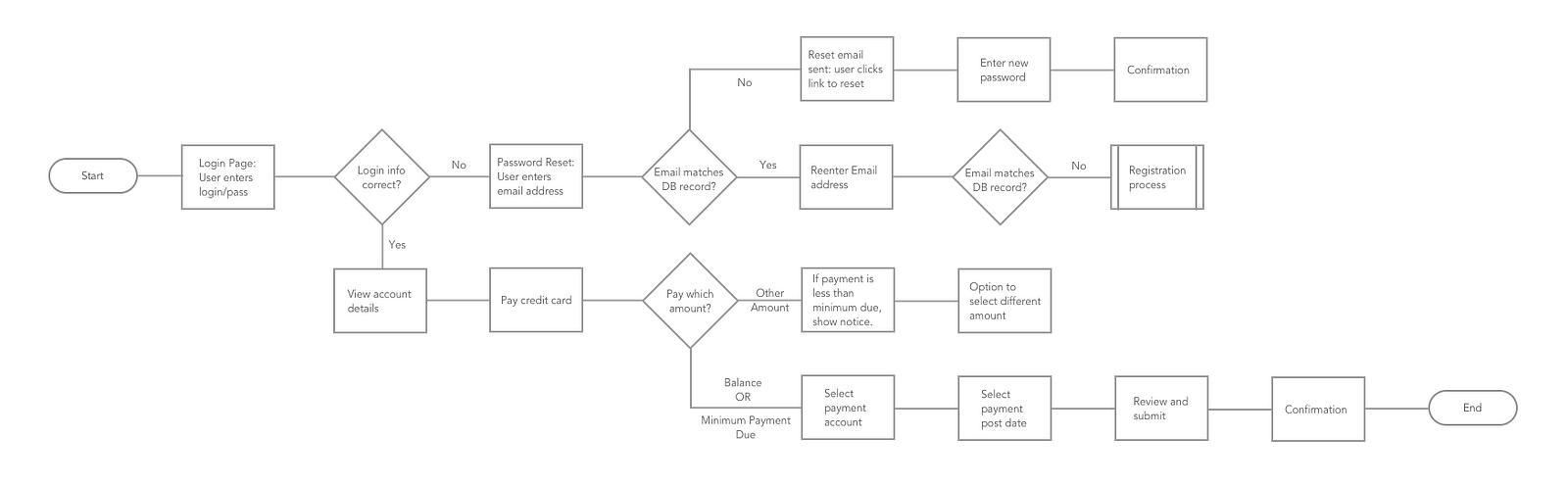
Flowchart is a diagram of the sequence of movements or actions of people or things involved in a complex system or activity.
Task/User flow
Task Flow
Task flow is a single flow completed similarly by all users for a specific action. Ex. Sign Up. Task flows have a singular flow, they don’t branch out.
User Flow
User Flow is the path a user follows through an application. I like to think of them as mini user journeys. The flow doesn’t have to be linear, it can branch out in a non-linear path. By determining this path you can see possible turns through the route and can optimize the user experience.
User flows can start off simple and help determine ‘red routes’ — key user journeys. These can easily evolve into complex flows when there are many conditions and requirements involved. User flows are helpful in hashing out complex flows before building out the product.
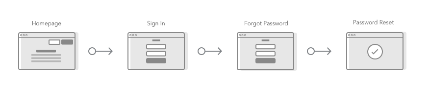
Wireflows
Design-specification format that combines wireframe-style page layout designs with a simplified flowchart-like way of representing interactions. — NNgroup
Wireframes alone are not enough. Wireframes communicate layout and static content but not interactions. Flowcharts do cover interactions in detail, but they leave out the user context. Wireflows help document complex interactions where the content or layout is changing on a few pages.
![]() https://www.nngroup.com/articles/wireflows/
https://www.nngroup.com/articles/wireflows/
Wireflows Document Interactions
The classic use-case for wireflows is to document the process of a user working through a common task on the product (e.g. “send a direct message to someone in your network” on a social media app). At each step in the workflow a simple wireframe or high fidelity screen mock-up shows the screen available to users.
An arrow is used to indicate the specific UI component where the user takes action (such as a tap on a button, click on a link, and so forth), and points to another wireframe image of what happens as a result of the interaction. The second "node" of that interaction need not be a separate page or screen; rather, it can show the same page with the result of that interaction, such as content that has changed, or feedback that the interface shows as a result of the interaction (e.g., a confirmation popup, a color change, or an error message). It's important that the arrows clearly indicate the clickable “hotspots” (or targets) that lead to the next step in the flow, in order to lessen ambiguity in the wireflow. Unambiguously indicating the triggering hotspot is particularly important for complex apps that have multiple actionable targets on a single page.
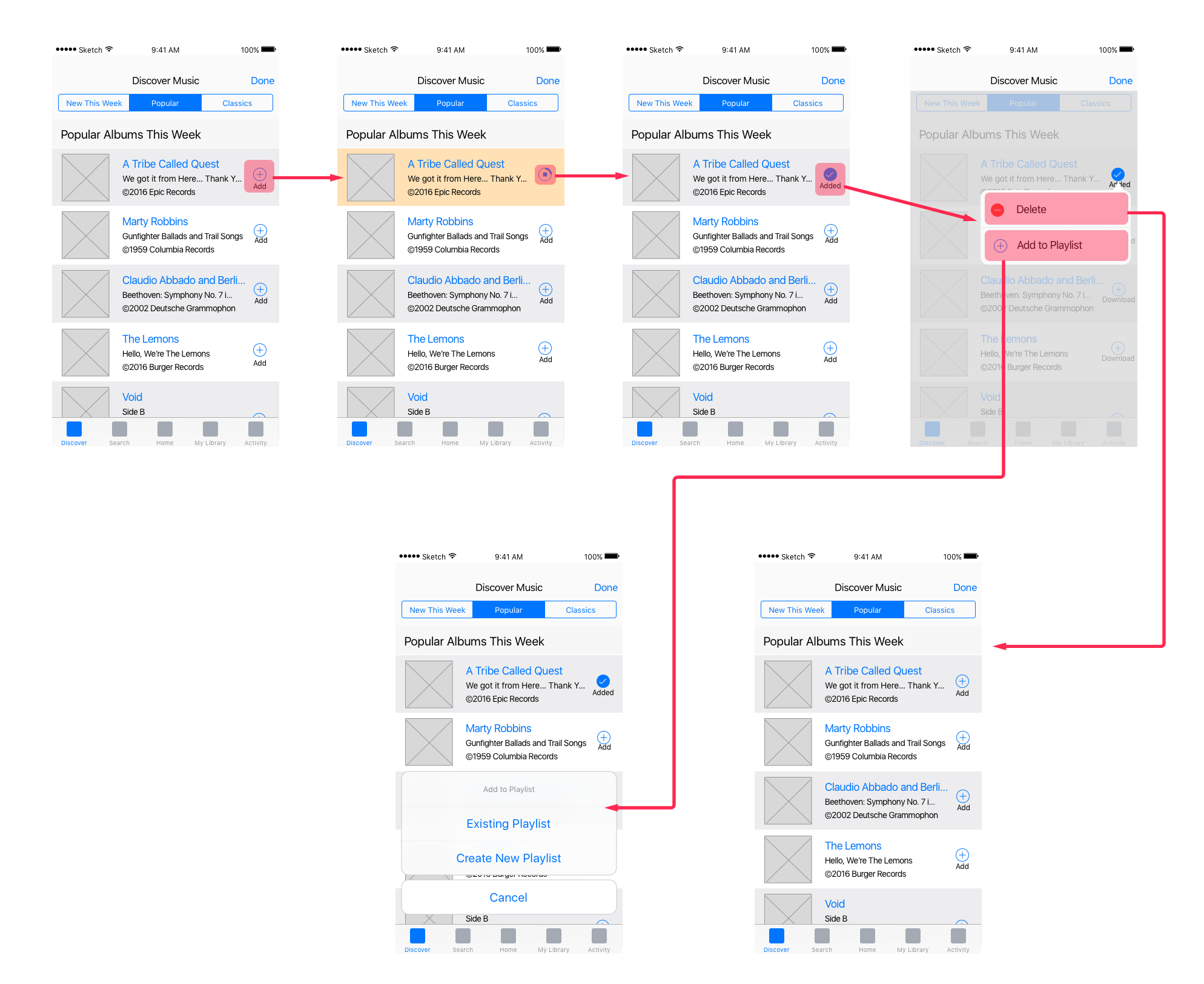
This simple wireflow shows a sequence of several mobile-app wireframes for a typical user-task flow. In this example, each wireframe corresponds to the same app page, rather than representing different app pages. Each step clearly indicates the hotspots that connect to the next step in the task flow. In addition, the wireflow shows the use of visual feedback in the second step (where the clicked album changes background color to register the tap).
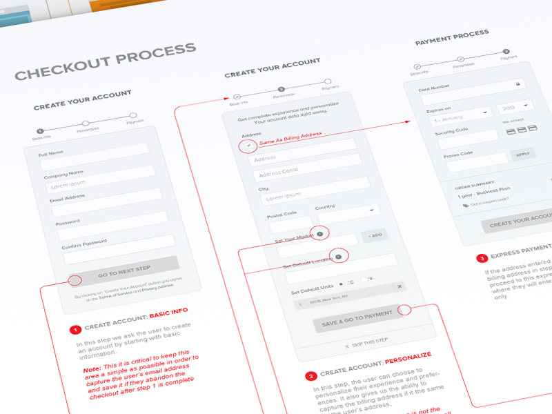
Despite being most frequently used for mobile apps, wireflows are also useful for documenting complex workflows in desktop application and webapps. Since showing a full-screen desktop wireframe for each step in a process can waste a lot of space if most of the screen design stays unchanged at each step, showing only the portion of the screen that changes (such as a dialog box, modal, filters or facets) in each step can be sufficient to document relevant, changing parts of the interface, while still providing enough context.
![]() https://medium.com/sketch-app-sources/user-journey-maps-or-user-flows-what-to-do-first-48e825e73aa8
https://medium.com/sketch-app-sources/user-journey-maps-or-user-flows-what-to-do-first-48e825e73aa8
Maps
Journey Map?
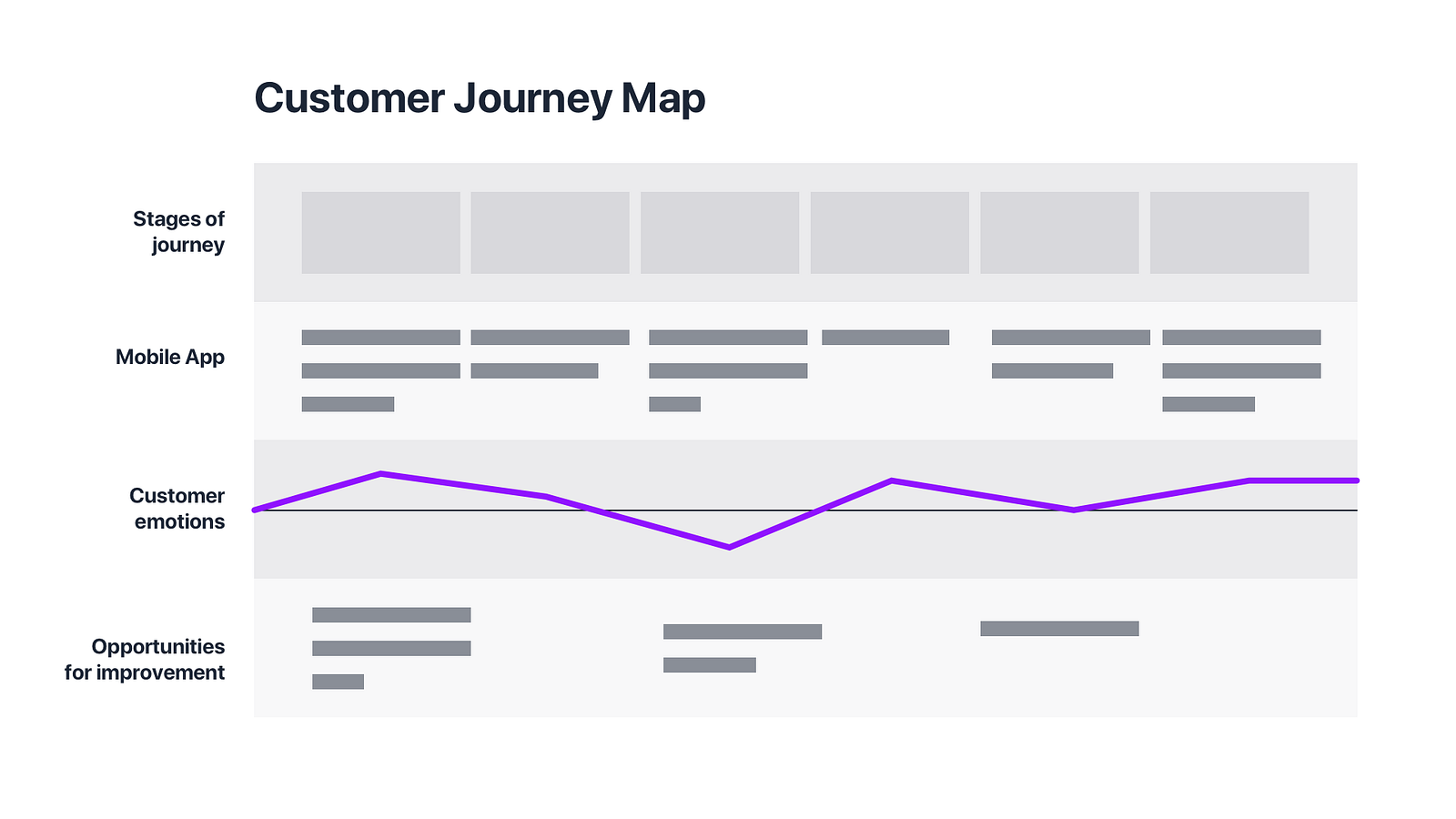
Journey Maps try to capture the experience of a user during the interaction with the products. They are a visual trip of the user across the solution. Journey Maps are some kind of a journal, where user notes their feelings, pain points and the moments of delight.
User Journey Maps may have several layers, they do not focus only on a particular element that triggers action. They can even describe what the back-end system makes to deliver data needed by the user. On the other hand, they can focus more on a user — describe their feeling, thoughts, what they while interacting with the product.
Journey maps are usually linear because they describe various aspects of accomplishing particular tasks.
![]() https://uxmisfit.com/2018/01/15/ui-flows-tool-for-better-communication-with-clients-and-team/
https://uxmisfit.com/2018/01/15/ui-flows-tool-for-better-communication-with-clients-and-team/
"If one picture is worth thousand words, then UI flows are worth a thousand pictures."
UI Flow
UI Flow is a type of deliverables prepared during UX design process. It has a purpose to visualize the way the user interacts with the interface in a glanceable way. They are hybrid between traditional flow charts with some visual interfaces included in them. Some designers call it IX Flows because they effectively visualize interactions. NNGroup calls it Wireflowsbecause wireframes are quick UI deliverables to include.
However, we can call them simply – UI Flows, because they include sort of graphical user interfaces that visualize the flow or path that user has to pass during the interaction with the solution.
UI Flows contain the following elements:
- User Interface (Mockups or Wireframes) – while in my opinion wireframes are a bit redundant (if you are curious why – read more) they do the nice job in UI Flows. However, I prefer to build UI Flows with mockups. Modern software tools like Sketch allows us to create high fidelity mockups quickly, they may be used successfully in UI Flows.
- Trigger Nodes – the entry point, UI element where user start interaction
- Decision nodes – if there are any constraints or rules that complicate the flow it is necessary to visualize them with conditional
- Target Nodes – the exit points, elements that point the result or destination of triggered action
- Loops – if there is a flow that is repeatable it is good to visualize its lifecycle.
- Modes – if the screen has got more than one state, there should be a visualization of the particular case. The mode can be a part of the screen not separate screen itself if the alternative state does not differ much from the original one.
- Connections – to visualize the flow all of these elements have to be connected together. Connections are usually arrows that connect trigger nodes and target nodes.
This is a reflection of main interaction elements – trigger, rules, feedback, modes/loops. Thanks to this UI Flows are really efficient when there is a need to demonstrate the usage process of the app or website.
UI Flows is the smart combination of mockups or wireframes with flow charts.
User Flow is the complete path that users follow across the whole solution. It is similar to user journeys. However it may not be linear, decision paths, modes, and loops show all possible interactions with the product.
Task Flow is the single path that illustrates a journey of a user to accomplish the particular task. They focus on one activity for example – creating a new password. They are often an attachment to a traditional text-based documentation, because of the ability to analyze single scenario or flow.
UI Flows may be used successfully to visualize User and Task Flows. Both of these techniques focus on presenting features and interactions, not pages. Thanks to adding some UI they will become more readable. The whole concept of the product will become more understandable.
Better than Prototypes?
There are some cases when UI Flows may work better than prototypes. If your client or team needs a quick glanceable deliverable to check if they understand solution well, there is no better part of product documentation than User flow diagrams.
Prototype requires interactions: scrolling, taps, swipes – all of this takes precious time. If someone would like to see the big picture of the solution diagram will do the work more efficiently.
User flows are very useful deliverables. However, do not think that prototypes are redundant. They are very important. Prototypes give the opportunity to validate our solution before it is built by showing how the product will work.
Summary
Agile and Lean methodologies encourage to make as little documentation as possible but as much ass necessary. UI Flows are the type of deliverables that clarify and effectively visualize the concept of the solution.
If you have not tried to prepare UI Flows, you should try to involve them in your next project. This may be a perfect occasion to confirm vision of the stakeholders. Make the whole design more understandable to your team members and save some time. If you are Sketch user I encourage you to try SQUID to create flows.
Decision Tree
In a decision tree, a flow of activities are not considered. Only decision making points and it's outcomes (and their decision points and their outcomes etc) are considered. This is helpful in taking quick decisions for a fairly medium complex problem.
Flow Chart
A flow chart is conventionally a set of activities which may or may not involve decision making at all. A flow chart, as the name suggests, in principle depicts the sequence of the activities to be carried out in a particular process. A flow chart can be used to depict the sequence of activities in any size of the process. Advance techniques of flow charts (like swim-lane flow charts) are available to map highly complex processes.
![]() https://uxplanet.org/an-introduction-to-interaction-flows-a4f783402529
https://uxplanet.org/an-introduction-to-interaction-flows-a4f783402529
Microinteractions
Triggers: the user-initiated or system-initiated action that starts the microinteraction (Example: a submit button, a light switch)
Rules: the capabilities and constraints in the microinteraction; what can and cannot be done in a microinteraction (Example: a date picker for an airline allows you to select departure and returns dates but neither date can be in the past)
Feedback: the visual cues that tell the user what is happening (Example: a red warning icon appears when the user’s password is incorrect, the flash on the screen when a user takes a screenshot, the dwindling character count as you type out your tweet)
Loops: the repeatability and lifecycle of a microinteraction (Example: a software update modal will pop up whenever your device detects that a new update is available)
Modes: the different versions or states of an element (Example: a read-only mode versus an edit-mode)
Nielsen and Norman Group: Wireflows
I also just happened to run across this article on Nielsen and Norman on Wireflows, which argued for the fusion of user/task flows and wireframes. While they show processes and relationships in a simple way, user flows don’t show how the visual elements provide entry points into each page or how they facilitate the user’s goals. Wireframes are great for laying out those visual elements, but by themselves, they are not very descriptive of the relationship or flow between pages.
The wireflow idea was a great solution that shows both the flow and the layouts but there was still a gap between how I envisioned the page to behaveversus how the developer would interpret it. The details were still not there.
I looked back on the framework from Dan Saffer’s book and thought: why not combine these two awesome approaches? Why not define the triggers/rules/feedback/loops/modes in the wireflow?
The IX Flow
An IX Flow is a wireflow that utilizes Saffer’s framework to define each interactive element’s trigger, feedback, rules, and loops/modes.
References/Research
- https://uxplanet.org/ux-glossary-task-flows-user-flows-flowcharts-and-some-new-ish-stuff-2321044d837d
- https://medium.com/sketch-app-sources/user-journey-maps-or-user-flows-what-to-do-first-48e825e73aa8
- https://uxmisfit.com/2018/01/15/ui-flows-tool-for-better-communication-with-clients-and-team/
- https://www.nngroup.com/articles/wireflows/
- https://www.quora.com/What-is-the-difference-between-a-decision-tree-and-a-flow-chart-apart-from-how-they-are-drawn
- https://uxplanet.org/an-introduction-to-interaction-flows-a4f783402529